Technical drawings are a crucial part of engineering, architecture, and other professions. They help visualize complex systems and processes that can't be seen with the naked eye.
In this article, we'll take a deep dive into technical drawings so you can understand what they're all about. You'll learn about the various types of technical drawings, the tools used to create them, as well as symbols and conventions for accurately conveying detailed information.
We'll also discuss commonly-used software programs, tips for reading and interpreting technical drawings, and the benefits of using these valuable documents.
Read on to discover everything you need to know about technical drawings!
Overview of Technical Drawings
Technical drawings are essential for creating complex projects. Let's take a closer look at what they're all about!
Technical drawings are visual representations that communicate ideas and instructions. They provide detailed information about an object or system's size, shape, and other characteristics. Technical drawings are used in various fields, such as engineering, architecture, manufacturing, and construction.
They help designers and engineers visualize their designs before building them. Technical drawings also allow for precise measurements when constructing objects or systems. By using technical drawings, designers and engineers can ensure that their projects will meet desired specifications.
Types of Technical Drawings
You'll be amazed at the vast variety of types of drawings out there! Technical drawings come in many shapes and sizes, and their variations are almost endless.
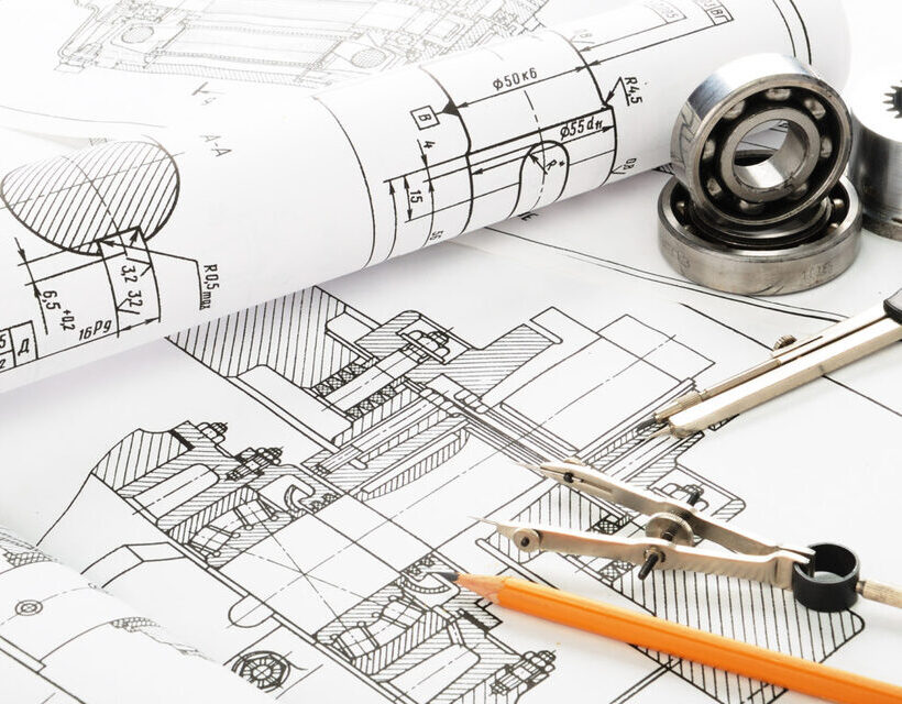
There are three main categories of technical drawings: assembly, detail, and section. Assembly drawings show how parts fit together to form a larger object, like an engine or machine. Detail drawings provide information about specific parts that make up an object, such as measurements and tolerances for bolts or screws. Section drawings illustrate what happens inside a component by showing it cut open along different planes or angles.
In addition to these primary types, there are several specialized forms of technical drawing, such as electrical diagrams, piping diagrams, architectural plans, engineering schematics, and more. Each type has its own unique set of rules that must be followed for the drawing to be accurate and useful.
Learning the fundamentals of each type is essential for creating effective technical drawings that accurately represent your ideas or designs.
Tools Used to Create Technical Drawings
Exploring the tools used to create technical drawings can help you gain a better understanding of the complexities behind them. It's helpful to think of these tools as the artists' paintbrushes; they make it possible for draftsmen and designers to bring their ideas into reality.
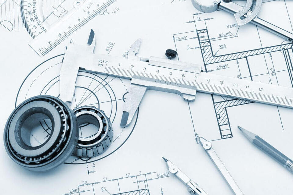
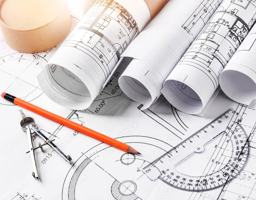
From simple pencils and rulers to more advanced software programs, there are many options available for anyone looking to perfect their technique. For those just starting out, basic drawing materials like graph paper, erasers, compasses, T-squares, and protractors are essential.
Digital drafting tools include Computer Aided Design (CAD) software, which allows users to create complex 3D models with precision accuracy. CAD also offers features such as layer management, which makes it easier for multiple people to work together on a single design project.
Ultimately, having the right tools is essential when creating technical drawings in order to achieve desired results in terms of accuracy and realism.
Symbols and Conventions Used in Technical Drawings
Understanding the symbols and conventions used in technical drawings is key to creating accurate designs. From line types that identify different parts of your design, to lettering styles that provide information about dimensions and other specifications, there are a few essential aspects you must understand when interpreting technical drawings.
Here's a breakdown of some of the most important symbols and conventions used:
- Lines: Different lines indicate different function within your design. For example, thin continuous lines denote visible outlines while dashed lines represent hidden features.
- Shading: Solid black shading indicates darker parts of your design, while cross-hatched shading typically represents sections to be cut away or removed from the piece as a whole.
- Arrows: Arrows can represent several things depending on their position on the drawing but usually indicate movement or direction.
- Lettering Styles: Technical drawings often feature standard lettering styles such as Roman letters (A,B,C) for angles and Greek letters (α, β) for arcs. In addition to providing measurements for each section of your design, these lettering styles also signify how each component fits together with others in order to create an effective final product.
- Dimension Lines: Dimension lines are typically parallel solid lines with short arrows at either end indicating the measurement between them. Knowing what dimension line length corresponds with which part of your drawing is critical in ensuring accuracy throughout the entire process!
By familiarizing yourself with all these symbols and conventions used in technical drawings, you'll soon be able to easily interpret them like clockwork! Understanding these concepts will help make translating plans into tangible objects much easier so you can bring ideas from concept to reality!
The Importance of Accuracy and Detail
Accurately interpreting technical drawings is crucial to creating effective designs, so always pay close attention to the details! It's important to take your time and double-check the measurements and symbols on a drawing before starting work. Even small mistakes can have big consequences down the road, causing costly delays and requiring additional resources.
Investing in a quality drafting program or architectural software can help you create more accurate drawings from the beginning. This will save time, money, and effort in the long run.
When reading a technical drawing, make sure that all of its components are precise and up-to-date. Check for any inconsistencies between different views of an object or discrepancies between dimensions listed in different places on the page.
The more accurate your final product, the better it will perform in its intended environment. As such, treating every detail with care is essential for achieving success when working with technical drawings.
Commonly Used Software Programs
Gaining familiarity with commonly-used software programs is key to efficiently working with technical drawings. Whether you're a seasoned engineer or just getting started in the field, there are several reliable software solutions available to help you create accurate and detailed technical drawings.
CAD (Computer Aided Design) software is a popular choice among professionals and hobbyists alike. This type of program provides users with an interactive environment where they can design, edit, and render their projects in near real-time speeds. Additionally, CAD software has powerful tools such as 3D modelling that allow users to easily visualize their designs from different angles and perspectives.
Other programs such as AutoCAD produce high-quality technical drawings using specialized features like snap grids and object snaps. These make it easier for users to accurately measure distances between objects on the drawing canvas and provide engineers with creative freedom when designing complex projects such as circuit boards or large infrastructure systems.
By becoming familiar with these commonly used software programs, you'll be able to confidently work through your technical drawing projects without any hiccups!
Tips for Reading and Interpreting Technical Drawings

Getting a grip on technical drawings can feel daunting, but with the right knowledge and practice, you'll be reading them like an expert in no time.
First, it's important to understand the different types of drawings that exist. These include pictorial representations such as orthographic projections, isometric diagrams, and axonometric illustrations. Schematic drawings, such as block diagrams or wiring schematics, are another type. Lastly, engineering drawings are used for manufacturing parts and components.
Once you know what type of drawing you're looking at, take some time to familiarize yourself with the common symbols used in technical drawings. These symbols usually represent measurements, dimensions, angles, and other specifications related to the object being drawn.
Finally, practice makes perfect when it comes to interpreting technical drawings! Familiarizing yourself with the tools used to create them will help you understand how they work better. You should also study up on any industry standards related to your specific field of work so that you can accurately read even more complex diagrams.
With patience and dedication, anyone can learn how to decipher technical drawings. Just remember that success takes time!
The Benefits of Using Technical Drawings
Using technical drawings can provide many advantages in a variety of contexts. They are invaluable tools for a wide range of industries and applications, from visualizing complex ideas to providing an accurate interpretation of plans. As such, there are numerous benefits to utilizing technical drawings that make them the go-to choice for designers, engineers, architects, and other professionals.
Firstly, technical drawings are incredibly precise. With exact measurements and specifications captured on paper or electronically, there's no room for misinterpretation or guesswork. This ensures that the job is done right the first time. Additionally, these precise diagrams allow for quick changes or modifications if needed without having to start from scratch.
Furthermore, technical drawings offer more than just accuracy. They also enable team members working from different locations to collaborate on projects successfully with minimal risk of miscommunication or confusion about details. This makes them an excellent tool for remote teams.
Finally, using technical drawings can help save time and money in the long run due to their efficiency and cost-effectiveness compared to traditional methods such as hand sketches and manual calculations. Technical drawing is clearly an essential tool in any professional's arsenal!
Conclusion
You've come so far in understanding technical drawings! Now that you know the different types of drawings, tools to create them, symbols and conventions that are used, and even software programs you can use, reading and interpreting them is easier with practice.
Technical drawings are an invaluable tool for designing projects due to their accuracy and detail. With this knowledge, your projects will soar to new heights! It's a great feeling being able to 'read' technical drawings - like a bird taking flight from its nest.
So, get out there and start creating those amazing projects!